


2017年9月6日 星期三
2017年9月5日 星期二
Lesson 5. Arduino Passive Buzzer
In this lesson, you will learn how to use a passive buzzer.
The purpose of the experiment is to generate eight different sounds, each sound lasting 0.5 seconds: from Alto Do (523Hz), Re (587Hz), Mi (659Hz), Fa (698Hz), So (784Hz), La (880Hz), Si (988Hz) to Treble Do (1047Hz).
The purpose of the experiment is to generate eight different sounds, each sound lasting 0.5 seconds: from Alto Do (523Hz), Re (587Hz), Mi (659Hz), Fa (698Hz), So (784Hz), La (880Hz), Si (988Hz) to Treble Do (1047Hz).
Component Required:
(1) x Sintron Uno R3
(1) x Passive buzzer
(2) x F-M wires (Female to Male DuPont wires)
Component Introduction
Passive Buzzer:
The working principle of passive buzzer is using PWM generating audio to make the air to vibrate. Appropriately changed as long as the vibration frequency, it can generate different sounds. For example, sending a pulse of 523Hz, it can generate Alto Do, pulse of 587Hz, it can generate midrange Re, pulse of 659Hz, it can produce midrange Mi. By the buzzer, you can play a song.
We should be careful not to use the UNO R3 board analog Write () function to generate a pulse to the buzzer, because the pulse output of analog Write () is fixed (500Hz).


code : ( please copy and upload sketch to arduino board )
(1) x Sintron Uno R3
(1) x Passive buzzer
(2) x F-M wires (Female to Male DuPont wires)
Component Introduction
Passive Buzzer:
The working principle of passive buzzer is using PWM generating audio to make the air to vibrate. Appropriately changed as long as the vibration frequency, it can generate different sounds. For example, sending a pulse of 523Hz, it can generate Alto Do, pulse of 587Hz, it can generate midrange Re, pulse of 659Hz, it can produce midrange Mi. By the buzzer, you can play a song.
We should be careful not to use the UNO R3 board analog Write () function to generate a pulse to the buzzer, because the pulse output of analog Write () is fixed (500Hz).
Schematic

Wiring diagram

Everything between /* and */ or after // is a block comment; it explains what the sketch is for.
Before you can run this, make sure that you have installed the <pitches> library or
re-install it, if necessary. Otherwise, your code won't work.
//by Sintron
//2017.03.20
#include "pitches.h"
// notes in the melody:
int melody[] = {
NOTE_C5, NOTE_D5, NOTE_E5, NOTE_F5, NOTE_G5, NOTE_A5, NOTE_B5, NOTE_C6};
int duration = 500; // 500 miliseconds
int buzzer = 12 ;// setting controls the digital IO foot buzzer
void setup() {
pinMode (buzzer, OUTPUT) ;// set the digital IO pin mode, OUTPUT out of Wen
}
void loop() {
for (int thisNote = 0; thisNote < 8; thisNote++) {
// pin8 output the voice, every scale is 0.5 sencond
tone(8, melody[thisNote], duration);
// Output the voice after several minutes
delay(1000);
}
// restart after two seconds
delay(2000);
}
note: pitches.h is as below :
you can create a new tab and then you can upload it together .that's to say : code in tab 1,and pitches.h in tab 2.
/*************************************************
* Public Constants
*************************************************/
#define NOTE_B0 31
#define NOTE_C1 33
#define NOTE_CS1 35
#define NOTE_D1 37
#define NOTE_DS1 39
#define NOTE_E1 41
#define NOTE_F1 44
#define NOTE_FS1 46
#define NOTE_G1 49
#define NOTE_GS1 52
#define NOTE_A1 55
#define NOTE_AS1 58
#define NOTE_B1 62
#define NOTE_C2 65
#define NOTE_CS2 69
#define NOTE_D2 73
#define NOTE_DS2 78
#define NOTE_E2 82
#define NOTE_F2 87
#define NOTE_FS2 93
#define NOTE_G2 98
#define NOTE_GS2 104
#define NOTE_A2 110
#define NOTE_AS2 117
#define NOTE_B2 123
#define NOTE_C3 131
#define NOTE_CS3 139
#define NOTE_D3 147
#define NOTE_DS3 156
#define NOTE_E3 165
#define NOTE_F3 175
#define NOTE_FS3 185
#define NOTE_G3 196
#define NOTE_GS3 208
#define NOTE_A3 220
#define NOTE_AS3 233
#define NOTE_B3 247
#define NOTE_C4 262
#define NOTE_CS4 277
#define NOTE_D4 294
#define NOTE_DS4 311
#define NOTE_E4 330
#define NOTE_F4 349
#define NOTE_FS4 370
#define NOTE_G4 392
#define NOTE_GS4 415
#define NOTE_A4 440
#define NOTE_AS4 466
#define NOTE_B4 494
#define NOTE_C5 523
#define NOTE_CS5 554
#define NOTE_D5 587
#define NOTE_DS5 622
#define NOTE_E5 659
#define NOTE_F5 698
#define NOTE_FS5 740
#define NOTE_G5 784
#define NOTE_GS5 831
#define NOTE_A5 880
#define NOTE_AS5 932
#define NOTE_B5 988
#define NOTE_C6 1047
#define NOTE_CS6 1109
#define NOTE_D6 1175
#define NOTE_DS6 1245
#define NOTE_E6 1319
#define NOTE_F6 1397
#define NOTE_FS6 1480
#define NOTE_G6 1568
#define NOTE_GS6 1661
#define NOTE_A6 1760
#define NOTE_AS6 1865
#define NOTE_B6 1976
#define NOTE_C7 2093
#define NOTE_CS7 2217
#define NOTE_D7 2349
#define NOTE_DS7 2489
#define NOTE_E7 2637
#define NOTE_F7 2794
#define NOTE_FS7 2960
#define NOTE_G7 3136
#define NOTE_GS7 3322
#define NOTE_A7 3520
#define NOTE_AS7 3729
#define NOTE_B7 3951
#define NOTE_C8 4186
#define NOTE_CS8 4435
#define NOTE_D8 4699
#define NOTE_DS8 4978
Lesson 4. arduino Control Active Buzzer
In this lesson, you will learn how to generate a sound with an active buzzer.
Component Required:
(1) x Sintron Uno R3
(1) x Active buzzer
(2) x F-M wires (Female to Male DuPont wires)
(1) x Sintron Uno R3
(1) x Active buzzer
(2) x F-M wires (Female to Male DuPont wires)
Component Introduction

BUZZER:
Electronic buzzers are DC-powered and equipped with an integrated circuit. They are widely used in computers, printers, photocopiers, alarms, electronic toys, automotive electronic devices, telephones, timers and other electronic products for voice devices. Buzzers can be categorized as active and passive ones. Turn the pins of two buzzers face up. The one with a green circuit board is a passive buzzer, while the other enclosed with a black tape is an active one.
The difference between the two is that an active buzzer has a built-in oscillating
source, so it will generate a sound when electrified. A passive buzzer does not have such a source so it will not tweet if DC signals are used; instead, you need to use square waves whose frequency is between 2K and 5K to drive it. The active buzzer is often more expensive than the passive one because of multiple built-in oscillating
circuits.


code ( please copy and upload sketch to arduino board )

remember to remove sticker while using.
BUZZER:
Electronic buzzers are DC-powered and equipped with an integrated circuit. They are widely used in computers, printers, photocopiers, alarms, electronic toys, automotive electronic devices, telephones, timers and other electronic products for voice devices. Buzzers can be categorized as active and passive ones. Turn the pins of two buzzers face up. The one with a green circuit board is a passive buzzer, while the other enclosed with a black tape is an active one.
The difference between the two is that an active buzzer has a built-in oscillating
source, so it will generate a sound when electrified. A passive buzzer does not have such a source so it will not tweet if DC signals are used; instead, you need to use square waves whose frequency is between 2K and 5K to drive it. The active buzzer is often more expensive than the passive one because of multiple built-in oscillating
circuits.
Schematic

Wiring diagram

Wiring diagram


Everything between /* and */ or after // is a block comment; it explains what the sketch is for.
//by Sintron
//2017.03.20
const int buzzer = 12; //buzzer to arduino pin 12
void setup(){
pinMode(buzzer, OUTPUT); // Set buzzer - pin 12 as an output
}
void loop(){
tone(buzzer, 1000); // Send 1KHz sound signal...
delay(1000); // ...for 1 sec
noTone(buzzer); // Stop sound...
delay(1000); // ...for 1sec
}
Lesson 3. Digital Inputs
In this lesson, you will learn to use push buttons with digital inputs to turn an LED
on and off.
Pressing the button will turn the LED on; pressing the other button will turn the LED off.
Pressing the button will turn the LED on; pressing the other button will turn the LED off.
Component Required:
(1) x Sintron Uno R3
(1) x 830 Tie-points Breadboard
(1) x 5mm red LED
(1) x 220 ohm resistor
(2) x push switches
(7) x M-M wires (Male to Male jumper wires)
(1) x Sintron Uno R3
(1) x 830 Tie-points Breadboard
(1) x 5mm red LED
(1) x 220 ohm resistor
(2) x push switches
(7) x M-M wires (Male to Male jumper wires)
Component Introduction
PUSH SWITCHES:
Switches are really simple components. When you press a button or flip a lever, they connect two contacts together so that electricity can flow throughthem.
The little tactile switches that are used in this lesson have four connections, which can be a little confusing.
PUSH SWITCHES:
Switches are really simple components. When you press a button or flip a lever, they connect two contacts together so that electricity can flow throughthem.
The little tactile switches that are used in this lesson have four connections, which can be a little confusing.
Actually, there are only really two electrical connections. Inside the switch package,
pins B and C are connected together, as are A and D.


Schematic


Although the bodies of the switches are square, the pins protrude from opposite
sides of the switch. This means that the pins will only be far enough apart when they
are placed correctly on thebreadboard.
Remember that the LED has to have the shorter negative lead to the right.
code : ( please copy and upload sketch to arduino board )
//by Sintron
//2017.03.20
int ledPin = 5;
int buttonApin = 9;
int buttonBpin = 8;
byte leds = 0;
void setup()
{
pinMode(ledPin, OUTPUT);
pinMode(buttonApin, INPUT_PULLUP);
pinMode(buttonBpin, INPUT_PULLUP);
}
void loop()
{
if (digitalRead(buttonApin) == LOW)
{
digitalWrite(ledPin, HIGH);
}
if (digitalRead(buttonBpin) == LOW)
{
digitalWrite(ledPin, LOW);
}
}
Remember that the LED has to have the shorter negative lead to the right.
code : ( please copy and upload sketch to arduino board )
Everything between /* and */ or after // is a block comment; it explains what the sketch is for.
//by Sintron
//2017.03.20
int ledPin = 5;
int buttonApin = 9;
int buttonBpin = 8;
byte leds = 0;
void setup()
{
pinMode(ledPin, OUTPUT);
pinMode(buttonApin, INPUT_PULLUP);
pinMode(buttonBpin, INPUT_PULLUP);
}
void loop()
{
if (digitalRead(buttonApin) == LOW)
{
digitalWrite(ledPin, HIGH);
}
if (digitalRead(buttonBpin) == LOW)
{
digitalWrite(ledPin, LOW);
}
}
Load the sketch onto your UNO board. Pressing the left button will turn the LED on
while pressing the right button will turn it off.
The first part of the sketch defines three variables for the three pins that are to be used. The 'ledPin' is the output pin and 'buttonApin' will refer to the switch nearer the top of the breadboard and 'buttonBpin' to the other switch.
The 'setup' function defines the ledPin as being an OUTPUT as normal, but now we have the two inputs to deal with. In this case, we use the set the pinMode to be 'INPUT_PULLUP' like this:
pinMode(buttonApin, INPUT_PULLUP);
pinMode(buttonBpin, INPUT_PULLUP);
The pin mode of INPUT_PULLUP means that the pin is to be used as an input, but that if nothing else is connected to the input, it should be 'pulled up' to HIGH. In other words, the default value for the input is HIGH, unless it is pulled LOW by the action of pressing the button.
This is why the switches are connected to GND. When a switch is pressed, it connects the input pin to GND, so that it is no longer HIGH.
Since the input is normally HIGH and only goes LOW when the button is pressed, the logic is a little upside down. We will handle this in the 'loop'function.
void loop() {
if (digitalRead(buttonApin) == LOW)
{
digitalWrite(ledPin, HIGH);
}
if (digitalRead(buttonBpin) == LOW)
{
digitalWrite(ledPin, LOW);
}
}
In the 'loop' function there are two 'if' statements. One for each button. Each does an 'digitalRead' on the appropriate input.
Remember that if the button is pressed, the corresponding input will be LOW, if button A is low, then a 'digitalWrite' on the ledPin turns it on.
Similarly, if button B is pressed, a LOW is written to the ledPin.
Example picture

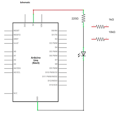
Lesson 2. about LED
In this lesson, you will learn how to change the brightness of an LED by using
different values of resistor.
Component Required:
(1) x Sintron Uno R3
(1) x 5mm red LED
(1) x 220 ohm resistor
(1) x 1k ohm resistor
(1) x 10k ohm resistor
(2) x M-M wires (Male to Male jumper wires)
In this lesson, you will use perhaps the most common of all LEDs: a 5mm red LED.
5mm refers to the diameter of the LED. Other common sizes are 3mm and 10mm.
You cannot directly connect an LED to a battery or voltage source because 1) the
LED has a positive and a negative lead and will not light if placed the wrong way and
2) an LED must be used with a resistor to limit or 'choke' the amount of current
flowing through it; otherwise, it will burnout!

Component Required:
(1) x Sintron Uno R3
(1) x 5mm red LED
(1) x 220 ohm resistor
(1) x 1k ohm resistor
(1) x 10k ohm resistor
(2) x M-M wires (Male to Male jumper wires)
Breadboards come in various sizes and configurations. The simplest kind is just a
grid of holes in a plastic block. Inside are strips of metal that provide electrical
connection between holes in the shorter rows. Pushing the legs of two different
components into the same row joins them together electrically. A deep channel
running down the middle indicates that there is a break in connections there,
meaning, you can push a chip in with the legs at either side of the channel without
connecting them together. Some breadboards have two strips of holes running
along the long edges of the board that are separated from the main grid. These have
strips running down the length of the board inside and provide a way to connect a
common voltage. They are usually in pairs for +5 volts and ground. These strips are
referred to as rails and they enable you to connect power to many components or
points in the board.
While breadboards are great for prototyping, they have some limitations. Because the connections are push-fit and temporary, they are not as reliable as soldered connections. If you are having intermittent problems with a circuit, it could be due to a poor connection on a breadboard.
LED:
LEDs make great indicator lights. They use very little electricity and they pretty much last forever.

If you do not use a resistor with an LED, then it may well be destroyed almost
immediately, as too much current will flow through, heating it and destroying the
'junction' where the light is produced.
There are two ways to tell which is the positive lead of the LED and which the negative.
Firstly, the positive lead is longer.
Secondly, where the negative lead enters the body of the LED, there is a flat edge to the case of the LED.
If you happen to have an LED that has a flat side next to the longer lead, you should assume that the longer lead is positive.
RESISTORS:
As the name suggests, resistors resist the flow of electricity. The higher the value of the resistor, the more it resists and the less electrical current will flow through it. We are going to use this to control how much electricity flows through the LED and therefore, how brightly it shines.

But first, more about resistors...
The unit of resistance is called the Ohm, which is usually shortened to Ω the Greek letter Omega. Because an Ohm is a low value of resistance (it doesn't resist much at all), we also denote the values of resistors in kΩ (1,000 Ω) and MΩ (1,000,000 Ω). These are called kilo-ohms and mega-ohms.
In this lesson, we are going to use three different values of resistor: 220Ω, 1kΩ and 10kΩ. These resistors all look the same, except that they have different colored stripes on them. These stripes tell you the value of the resistor.
The resistor color code has three colored stripes and then a gold stripe at one end.

Unlike LEDs, resistors do not have a positive and negative lead. They can be
connected either way around.
If you find this approach method too complicated, you can read the color ring flag on our resistors directly to determine its resistance value. Or you may use a digital multimeter instead.
If you find this approach method too complicated, you can read the color ring flag on our resistors directly to determine its resistance value. Or you may use a digital multimeter instead.


The UNO is a convenient source of 5 volts, which we will use to provide power to
the LED and the resistor. You do not need to do anything with your UNO, except to
plug it into a USB cable.
With the 220 Ω resistor in place, the LED should be quite bright. If you swap out the 220 Ω resistor for the 1kΩ resistor, then the LED will appear a little dimmer. Finally, with the 10 kΩ resistor in place, the LED will be just about visible. Pull the red jumper lead out of the breadboard and touch it into the hole and remove it, so that it acts like a switch. You should just be able to notice the difference.
At the moment, you have 5V going to one leg of the resistor, the other leg of the resistor going to the positive side of the LED and the other side of the LED going to GND. However, if we moved the resistor so that it came after the LED, as shown below, the LED will still light.
You will probably want to put the 220Ω resistor back in place.
It does not matter which side of the LED we put the resistor, as long as it is there somewhere

Lesson 0 How to upload code ( sketch ) to arduino board
for uploading sketch to Arduino board .there are 3 mains steps :
1.you need to install "Arduino IDE" .
2.you need to select correct board type .
3.the board needs to be detected by computer. ( com port for windows / cu.usbmodem...for Mac )
below are the video example :
1. for Mac:
1.you need to install "Arduino IDE" .
2.you need to select correct board type .
3.the board needs to be detected by computer. ( com port for windows / cu.usbmodem...for Mac )
below are the video example :
1. for Mac:
for Windows:
if everything going smoothly .you should see "Done Uploading" at then end .and while uploading .the board would flash RX & TX LEDs quickly.
Lesson 1. arduino Blink LED
The Arduino UNO R3 board has rows of connectors along both sides that are used to connect
to several electronic devices and plug-in 'shields' that extends its capability.
It also has a single LED that you can control from your sketches. This LED is built onto the UNO R3 board and is often referred to as the 'L' LED as this is how it is labeled on the board.

code ( please copy and upload sketch to your board )
/*
Blink
Turns on an LED on for one second, then off for one second, repeatedly.
This example code is in the public domain.
*/
// Pin 13 has an LED connected on most Arduino boards.
// give it a name:
int led = 13;
// the setup routine runs once when you press reset:
void setup() {
// initialize the digital pin as an output.
pinMode(led, OUTPUT);
}
// the loop routine runs over and over again forever:
void loop() {
digitalWrite(led, HIGH); // turn the LED on (HIGH is the voltage level)
delay(1000); // wait for a second
digitalWrite(led, LOW); // turn the LED off by making the voltage LOW
delay(1000); // wait for a second
}
Component Required:
(1) x Sintron Arduino-Compatible Uno R3
this is to show you how to control LED .you can think of it as a output device .after you practice this one .later you would know how to control and interact with other components.

code ( please copy and upload sketch to your board )
Everything between /* and */ or after // is a block comment; it explains what the sketch is for.
/*
Blink
Turns on an LED on for one second, then off for one second, repeatedly.
This example code is in the public domain.
*/
// Pin 13 has an LED connected on most Arduino boards.
// give it a name:
int led = 13;
// the setup routine runs once when you press reset:
void setup() {
// initialize the digital pin as an output.
pinMode(led, OUTPUT);
}
// the loop routine runs over and over again forever:
void loop() {
digitalWrite(led, HIGH); // turn the LED on (HIGH is the voltage level)
delay(1000); // wait for a second
digitalWrite(led, LOW); // turn the LED off by making the voltage LOW
delay(1000); // wait for a second
}
Component Required:
(1) x Sintron Arduino-Compatible Uno R3
2017年8月30日 星期三
Sintron arduino working with CH-926 coin acceptor to make money
with this arduino example ,you will learn how to read signals from CH-926 coin acceptor ,and then use LED to response .so alternatively .you can use coin acceptor to control any other device to charge fee for your service .
Wirings :

1. supply 12V power supply for both “coin acceptor” and “arduino uno”.

2. coin acceptor output pin ( white wire ) -- arduino pin D2 .
3. LED control pin : pin D8 ( add 220 ohm resistance between D8 & LED )
code :
int Ledpin = 8;
int Coinpin = 2 ;
void setup( )
{
pinMode(Ledpin,OUTPUT);
pinMode( Coinpin,INPUT);
}
void loop ( )
{
if (digitalRead( Coinpin) == HIGH)
{
digitalWrite(Ledpin,HIGH);
}
else if (digitalRead( Coinpin) == LOW)
{
digitalWrite(Ledpin,LOW);
}
}
code 2: updated on 2019 june, using interrupt method:
// by Sintron ccfeng june 2019
const byte builtinLED = 13;
const byte ledPin = 8;
const byte coin_input = 2;
volatile byte state = LOW;
boolean coin_flag = false ;
void setup() {
Serial.begin(9600);
pinMode(ledPin, OUTPUT);
pinMode(coin_input, INPUT_PULLUP);
attachInterrupt(digitalPinToInterrupt(coin_input), CH926, FALLING);
}
void loop() {
if (coin_flag == true )
{
delay (15);
state = !state;
digitalWrite(ledPin, state); // you can also use this for a relay
digitalWrite(builtinLED, state); // check if the bulit in LED changes
coin_flag = false ; // remove the flag
Serial.println("got a coin in"); // you can also check in serial monitor
}
}
void CH926() {
coin_flag = true;
}
Material list :
1. Sintron arduino-compatible board
2. Sintron CH-926 coin acceptor
3. LED
4. 220 ohm resistor *1
5. 12V power supply *1


